
Showing posts with label Physcis. Show all posts
Showing posts with label Physcis. Show all posts
22 Mar 2019
26 Jun 2017
CURRENT ELECTRICITY
Q-1 WHAT IS ELECTRIC CURRENT?
Electric Current (I)

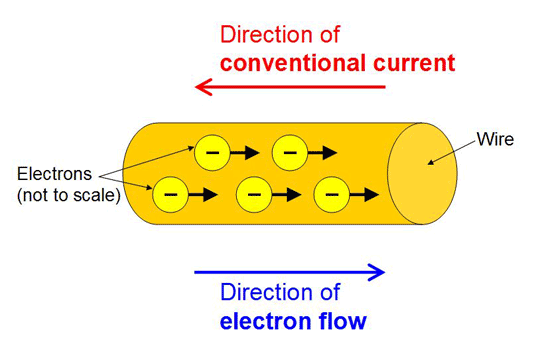
The rate of flow of charge through any cross-section of a wire is called electric current flowing through it.
Electric current (I) = q / t.
Its SI unit is ampere (A).
Q-2 WHAT IS CONVENTIONAL DIRECTION?Its SI unit is ampere (A).
The conventional direction of electric current is the direction of motion of positive charge.
- The current is the same for all cross-sections of a conductor of non-uniform cross-section.
- Similar to the water flow,
- charge flows faster where the conductor is smaller in cross-section and
- slower where the conductor is larger in cross-section, so that
- charge rate remains unchanged.
If a charge q revolves in a circle with frequency f,
the equivalent current,
the equivalent current,
i = qf
(In a metallic conductor current flows due to motion of free electrons while in electrolytes and ionized gases current flows due to electrons and positive ions.)
Types of Electric Current
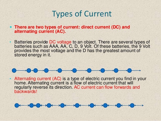


According to its magnitude and direction electric current is of two types
(i) Direct Current (DC) Its magnitude and direction do not change with time. A ceil, battery or DC dynamo are the sources of direct current.
(ii) Alternating Current (AC) An electric current whose magnitude changes continuously and changes its direction periodically is called alternating current. AC dynamo is source of alternating current.
Current Density


The electric current flowing per unit area of cross-section of conductor is called current density.
Current density (J) = I / A
Its S1 unit is ampere metre-2 and dimensional formula is [AT-2].
It is a vector quantity and its direction is in the direction of motion positive charge or in the direction of flow of current.
Thermal Velocity of Free Electrons


Free electrons in a metal move randomly with a very high speed of the order of 105 ms-1. This speed is called thermal velocity of free electron.
Average thermal velocity of free electrons in any direction remains zero.
When a potential difference is applied across the ends of a conductor, the free electrons in it move with an average velocity opposite to direction of electric field. which is called drift velocity of free electrons.
Drift velocity vd = eEτ / m = eVτ / ml
where, τ = relaxation time, e = charge on electron,
E = electric field intensity, 1 = length of the conductor,
V = potential difference across the ends of the conductor
m = mass of electron.
Relation between electric current and drift velocity is given by
vd = I / An e
Mobility


The drift velocity of electron per unit electric field applied is mobility of electron.
Mobility of electron (μ) = vd / E
Its SI unit is m2s-1V-1 and its dimensional formula is [M-1T2A].
Ohm’s Law
If physical conditions of a conductor such as temperature remains unchanged, then the electric current (I) flowing through the conductor is directly proportional to the potential difference (V) applied across its ends.
I ∝ V
or V = IR

where R is the electrical resistance of the conductor and R = Ane2 τ / ml.
Electrical Resistance
The obstruction offered by any conductor in the path of flow of current is called its electrical resistance.
Electrical resistance, R = V / I
Its SI unit is ohm (Ω) and its dimensional formula is [ML2T-3A-2].
Electrical resistance of a conductor R = ρl / A
where, l = length of the conductor, A = cross-section area and
ρ = resistivity of the material of the conductor.
Resistivity
Resistivity of a material of a conductor is given by
ρ = m / n2 τ
where, n = number of free electrons per unit volume.
Resistivity of a material depend on temperature and nature of the material.
It is independent of dimensions of the conductor, i.e., length, area of cross-section etc.
Resistivity of metals increases with increase in temperature as
ρt = ρo (1 + αt)
where ρo and ρt are resistivity of metals at O°C and t°C and α temperature coefficient of resistivity of the material.
For metals α is positive, for some alloys like nichrome, manganin and constantan, α is positive but very low.
For semiconductors and insulators. α is negative.
Resistivity is low for metals, more for semiconductors and very high alloys like nichrome, constantan etc.
(In magnetic field the resistivity of metals increases. But resistivity of ferromagnetic materials such as iron, nickel, cobalt etc decreases in magnetic field.)
Electrical Conductivity
The reciprocal of resistivity is called electrical conductivity.
Electrical conductivity (σ) = 1 / ρ = 1 / RA = ne2 τ / m
Its SI units is ohm-1 m-1 or mho m-1 or siemen m-1.
Relation between current density (J) and electrical conductivity (σ) is given by
J = σ E
where, E = electric field intensity.
Ohmic Conductors
Those conductors which obey Ohm’s law, are called ohmic conductors e.g., all metallic conductors are ohmic conductor.
For ohmic conductors V – I graph is a straight line.
Non-ohmic Conductors
Those conductors which do not obey Ohm’s law, are called non-ohmic conductors. e.g., diode valve, triode valve, transistor , vacuum tubes etc.
For non-ohmic conductors V – I graph is not a straight line.
Superconductors
When few metals are cooled, then below a certain critical temperature their electrical resistance suddenly becomes zero. In this state, these substances are called superconductors and this phenomena is called superconductivity.
Mercury become superconductor at 4.2 K, lead at 7.25 K and niobium at 9.2 K
Colour Coding of Carbon Resistors
The resistance of a carbon resistor can be calculated by the code given on it in the form of coloured strips.
This colour coding can be easily learned in the sequence “B B ROY Great Bratain Very Good Wife”.
Combination of Resistors
1.In Series
(i) Equivalent resistance, R = R1 + R2 + R3
(ii) Current through each resistor is same.
(iii) Sum of potential differences across individual resistors is equal to the potential difference, applied by the source.
2. In Parallel
Equivalent resistance
1 / R = 1 /R1 + 1 / R2 + 1 / R3
Potential difference across each resistor is same.
Sum of electric currents flowing through individual resistors is equal to the be electric current drawn from the source.
Electric Cell
An electric cell is a device which converts chemical energy into electrical energy.
Electric cells are of two types
(i) Primary Cells Primary ceUs cannot be charged again. Voltic, Daniel and Leclanche cells are primary cells.
(ii) Secondary Cells Secondary cells can be charged again and again. Acid and alkali accumulators are secondary cells.
Electro – motive – Force (emf) of a Cell
The energy given by a cell in flowing unit positive charge throughout the circuit completely one time, is equal to the emf of a cell.
Emf of a cell (E) = W / q.
Its SI unit is volt.
Terminal Potential Difference of a Cell
The energy given by a cell in flowing unit positive charge through till outer circuit one time from one terminal of the cell to the other terminal of the cell.
Terminal potential difference (V) = W / q.
Its SI unit is volt.
Internal Resistance of a Cell
The obstruction offered by the electrolyte of a cell in the path of electric current is called internal resistance (r) of the cell. Internal resistance of a cell
(i) Increases with increase in concentration of the electrolyte.
(ii) Increases with increase in distance between the electrodes.
(iii) Decreases with increase in area of electrodes dipped in electrolyte.
Relation between E. V and r
E = V + Ir
r = (E / V – 1) R
If cell is in charging state, then
E = V – Ir
Grouping of Cells
(i) In Series If n cells, each of emf E and internal resistance r are connected in series to a resistance R. then equivalent emf
[Image: CBSE Class 11 Physics Notes Current Electricity]
Eeq = E1 + E2 + …. + En = nE
Equivalent internal resistance req = r1 + r2 + …. + rn = nr
Current In the circuit I = Eeq / (R + req) = nE / (R + nr)
(ii) In Parallel If n cells. each of emf E and internal resistance r are connected to in parallel. then equivalent emf. Eeq = E
Equivalent internal resistance
1 / req = 1 / r1 + 1 / r1 + … + 1 / rn = n / r or req = r / n
Current In the circuit I = E / (R + r / n)
(iii) Mixed Grouping of Cells If n cells, each of emf E and internal resistance r are connected in series and such m rows are connected in parallel, then
Equivalent emf, Eeq
Equivalent Internal resistance req
Current in the circuit, I = nE / (R + nr / m)
or I = mnE / mR + nr
Note Current in this circuit will be maximum when external resistance is equal to the equivalent internal resistance, i.e.,
R = nr / m ⇒ mR = nr
Kirchhoff’s Laws
There are two Kirchhoff’s laws for solving complicated electrical circuits
(i) Junction Rule The algebraic sum of all currents meeting at a junction in a closed circuit is zero, i.e., Σ I = O.
This law follows law of conservation of charge.
(ii) Loop Rule The algebraic sum of all the potential differences in any closed circuit is zero, i.e.,
ΣV = 0 ⇒ ΣE = ΣIR
This law follows law of conservation of energy.
Balanced Wheatstone Bridge
Wheatstone bridge is also known as a metre bridge or slide wire bridge.
This is an arrangement of four resistance in which one resistance is unknown and rest known. The Wheatstone bridge as shown in figure. The bridge is said to be balanced when deflection in galvanometer is zero, i.e., ig = O.
Principle of Wheatstone Bridge
P / Q = R / S
The value of unknown resistance S can found. as we know the value of P,Q and R. It may be remembered that the bridge is most sensitive, when all the four resistances are of the same order.
Meter Bridge
This is the simplest form of Wheatstone bridge and is specially useful for comparing resistance more accurately.
R / S = l1 / (100 – l1)
where l1 is the length of wire from one end where null point is obtained.
Potentiometer
Potentiometer is an ideal device to measure the potential difference between two points. It consists of a long resistance wire AB of uniform cross section in which a steady direct current is set up by means of a battery.
If R be the total resistance of potentiometer wire L its total length, then potential gradient, i.e., fall in potential per unit length along the potentiometer will be
K = V / L = IR / L
= Eo R / (Ro + R)L
where, Eo = emf of battery and Ro = resistance inserted by means of rheostat Rh.
Determination of emf of a Cell using Potentiometer
If with a cell of emf E on sliding the contact point we obtain zero deflection in galvanometer G when contact point is at J at a length I from the end where positive terminal of cell have been joined. then fall in potential along length i is just balancing the emf of cell. Thus, we have
E = Kl
or E1 / E2 = l1 / l2
Determination of Internal Resistance of a Cell using Potentiometer
The arrangement is shown in figure. If the cell E is in open circuit and balancing length l1, then
E = Kl1
But if by inserting key K2 circuit of cell is closed, then ooten difference V is balanced by a length l2 of potential where
V = Kl2
Internal resistance of cell
r = E – V / V , R = l1 – l2 / l2 * R
Important Points
- Potentiometer is an ideal voltmeter.
- Sensitivity of potentiometer is increased by increasing length of potentiometer wire.
- If n identical resistances are first connected in series and then in parallel. the ratio of the equivalent resistance.
Rs / Rp= n2 / 1
- If a skeleton cube is made with 12 equal resistance,each having a resistance R, then the net resistance across
- The diagonal of cube = 5 / 6 R
- The diagonal of a face = 3 / 4 R
- along a side = 7 / 12 R
- If a resistance wire is stretched to a greater length, keeping volume constant, then
R ∝ l2 ⇒ R1 / R2 = (l1 / l2)2
and R ∝ 1 / r4 ⇒ R1 / R2 = (r2 / r1)4
where l is the length of wire and r is the radius of cross-section area of wire.


Subscribe to:
Posts (Atom)